
Introduction
What is a brake rotor? A brake rotor is the metal disc that turns with the wheel and gives the brake pads a surface to clamp, converting the vehicle’s motion into heat. It sounds simple, yet rotors are one of the parts most often ordered wrong, returned or blamed for problems they did not cause.
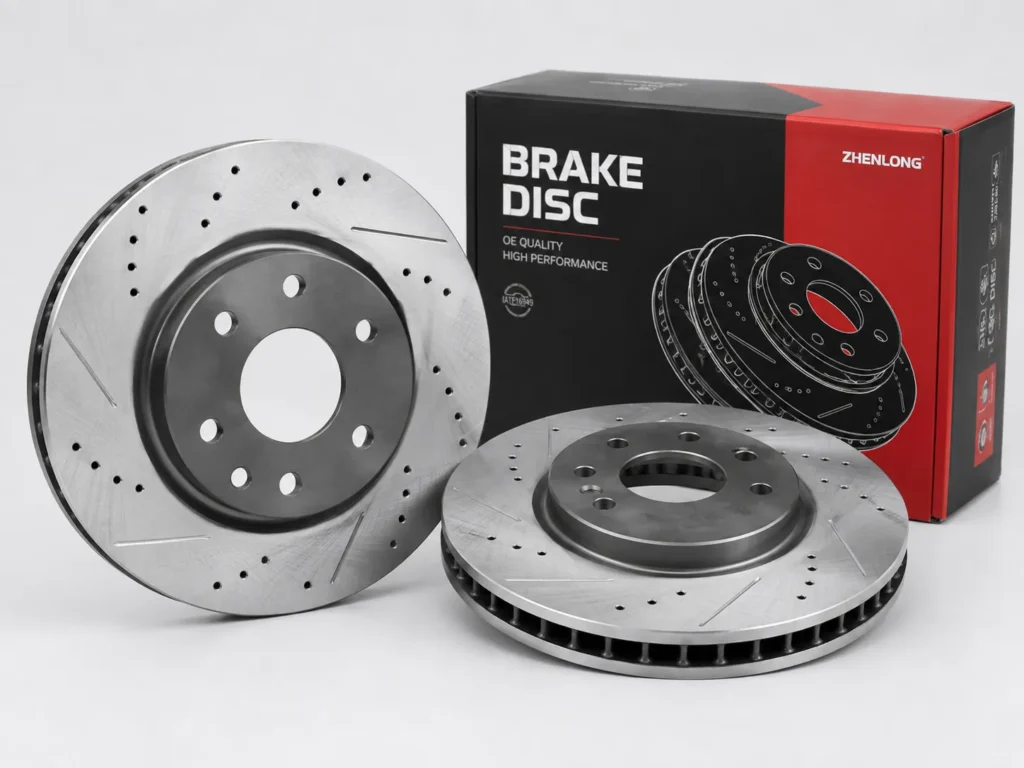
For an auto parts store, the challenge is that two rotors can look almost identical on the shelf and still fit different vehicles. For a repair shop, it is the customer who comes back with a pulsating pedal two months after a brake job. For a buyer, it is knowing which dimensions, tolerances and finishes belong on the purchase order.
This guide covers what a rotor is, how it works, its parts and materials, the main types, the dimensions that decide fitment, what runout and DTV really mean, the signs of rotor problems, when to replace, how pads and rotors work together, how rotors are made and inspected, and how to choose the correct replacement. We write as a brake rotor manufacturer, and where we share numbers from our own machining line or test lab, we say so.
01
What Is a Brake Rotor?
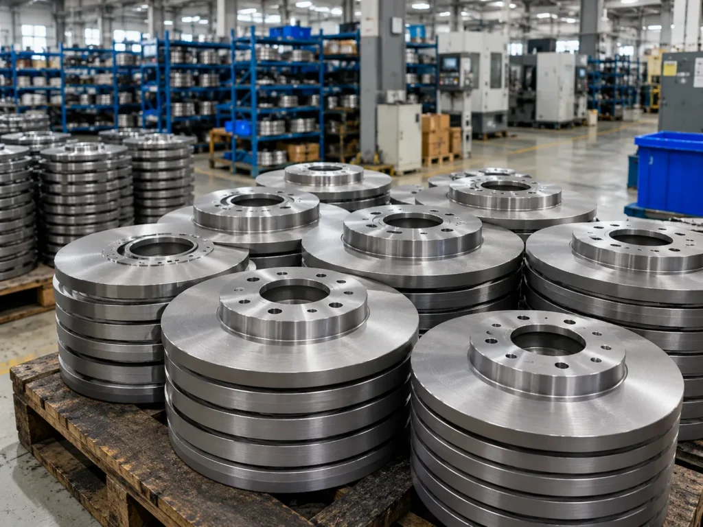
A brake rotor, also called a brake disc, is a round metal part bolted between the wheel hub and the wheel. When the driver brakes, the caliper squeezes two brake pads against both faces of the rotor, and the friction slows the wheel.
So, what are rotors on a car in practical terms? They are the large discs you can see through the spokes of most alloy wheels. What do rotors look like up close? A typical passenger-car rotor is a cast-iron disc about 250–350 mm across, with a raised center section (the “hat”) that carries the bolt holes. The flat outer ring is the friction surface. On a vented rotor, you will see a gap between the two friction faces, filled with cooling vanes. New rotors usually have a smooth, machined finish on the friction faces and a painted or coated hat and edge.
Where Is the Brake Rotor Located?
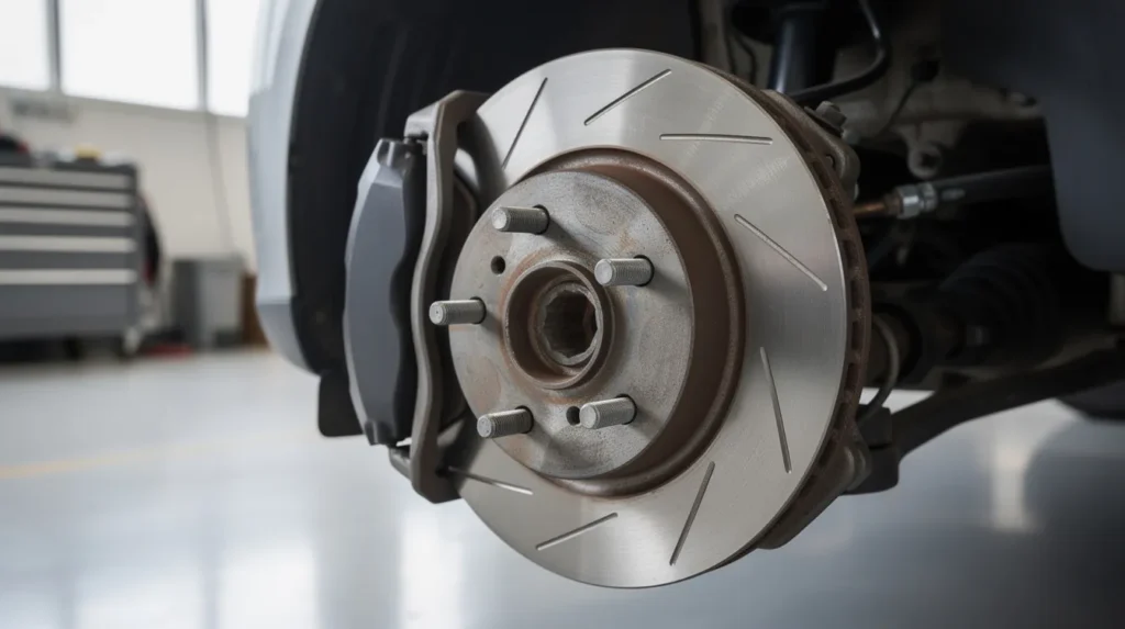
The rotor sits directly behind the wheel, mounted on the wheel hub. The wheel studs pass through the rotor’s hat, so the rotor is clamped between the hub and the wheel when the lug nuts are tightened. The caliper is mounted to the steering knuckle or axle bracket and straddles the outer edge of the rotor.
Most modern passenger cars use disc brakes on the front axle. Many also use them on the rear, while some economy cars and light trucks still use drum brakes at the rear. Some rear rotors also contain a small drum inside the hat for the parking brake, known as a drum-in-hat design.
What Does a Brake Rotor Do?
What do brake rotors do? They have three jobs
- Provide a friction surface. The rotor gives the pads a flat, stable surface to clamp on both sides.
- Absorb and release heat. Nearly all of the braking energy turns into heat, and most of it goes into the rotor before being released into the air.
- Stay dimensionally stable. The rotor must keep its thickness, flatness and runout within tight limits as it heats, cools and wears, or the driver feels vibration.
That third job is where most rotor complaints start. A rotor can still stop the car perfectly well and still cause a comeback if its geometry drifts.
02
How Does a Brake Rotor Work?
How Brake Pads Clamp the Rotor
The rotor and caliper work as a pair.
Here is what happens, step by step
- The driver presses the brake pedal, and the master cylinder pressurizes the brake fluid.
- Hydraulic pressure pushes the caliper piston or pistons outward.
- On a floating caliper, the piston pushes the inner pad against the rotor, and the caliper body slides on its guide pins to pull the outer pad against the other face. On a fixed caliper, pistons on both sides push both pads at the same time.
- The pads clamp the rotor from both sides with equal force, provided the rotor faces are parallel and the caliper slides are free.
- When the pedal is released, the pads relax and the rotor spins freely again.
Because the pads clamp both faces at once, the two faces must be parallel. If one area of the rotor is thicker than another, the pads are pushed apart and drawn together on every revolution. The driver feels that as pedal pulsation.
How Friction Converts Motion Into Heat
Braking turns kinetic energy into heat. A 2,000 kg SUV traveling at 100 km/h carries roughly 770 kJ of kinetic energy, and a full stop turns nearly all of it into heat within a few seconds. Most of that heat is generated at the pad-rotor interface and flows into the rotor, because the rotor has far more mass and surface area than the pads.
The front rotors take the largest share of the work, typically 60–70% of the braking effort on a passenger car, because weight shifts forward during braking. That is why front rotors are usually larger, thicker and vented.
How the Rotor Dissipates Heat
The rotor stores heat in its mass and releases it to the air by convection, radiation and conduction into the hub. A vented rotor pumps air through its vanes as it spins, which can increase cooling significantly compared with a solid rotor of the same diameter.
Industry Data — SAE International:
An SAE technical study on cast-iron brake rotors reported that rotor surface temperatures above 700°C are not unusual under heavy-duty disc-brake service, including heavy vehicles and high-performance passenger cars. The study also found that heat-induced microstructural transformation produced approximately 15% higher pad wear and roughly twice the rotor wear in the tested condition, even though braking performance did not change significantly. This helps explain why rotor material, thermal capacity and heat dissipation matter beyond simply providing a surface for the pads to clamp.
Source: J. P. Coyle & P. H. S. Tsang, SAE Technical Paper 830534, SAE International.
For buyers, the takeaway is practical. A rotor that is too light, too thin or poorly cooled for the application may still pass a fitment check, but it will run hotter, wear faster and wear the pads faster too.
03
What Are the Main Parts of a Brake Rotor?
The main parts of a rotor are the friction surface, the hat and hub mounting face, the cooling vanes (on vented rotors), and the rotor edge with its minimum thickness marking. The table below works as a simple brake rotor diagram in text form, from the outside in.
Friction Surface
The friction surface is the working area of the rotor. On a solid rotor it is one cast plate; on a vented rotor there are two plates, called cheeks, joined by vanes. It must be flat, with both faces parallel to each other and square to the hub mounting face.
The surface finish matters too. A rough, deeply tooled finish can cause noise and slow bedding, while a finish that is too smooth can make it harder for the pads to establish a transfer layer.
On the Spec Sheet
Specify thickness, parallelism (thickness variation), lateral runout and surface finish requirements, not just “machined faces.”
Rotor Hat and Hub Mounting Face
The hat is the raised center section that connects the friction ring to the hub. Its height sets where the friction ring sits relative to the caliper. The back of the hat is the hub mounting face, and it must be machined flat and square, because any error there is multiplied at the outer edge as runout.
Buyer Check
The mounting face should be clean bare metal or have only a coating designed for that area. Thick paint or coating on the mounting face can create runout on installation.
Cooling Vanes
On vented rotors, internal vanes connect the two friction plates. Straight radial vanes allow the same rotor to fit either side of the vehicle. Directional (curved) vanes pump air more efficiently but make the rotor side-specific, so a left rotor fitted on the right side cools poorly. Some designs use pillars or pins instead of vanes.
Buyer Check
For directional-vane rotors, confirm left and right part numbers are separate in your system and clearly marked on the box.
Rotor Edge and Minimum Thickness Marking
Most rotors carry a minimum thickness marking, usually stamped or cast as “MIN TH” followed by a value, such as “MIN TH 26.0 mm.” It is located on the hat or the edge. This is the thinnest the rotor may be in service. Below it, the rotor has too little mass to absorb heat and may crack or allow the caliper piston to over-extend.
You may also see small cuts machined into the outer edge. These are balancing cuts, used to correct the rotor’s mass distribution so it does not cause vibration at speed.
04
What Are Brake Rotors Made Of?
What are brake rotors made of? Almost all passenger-car and light-truck rotors are made of gray cast iron. High-carbon cast iron is used where noise and heat cracking are concerns, and carbon-ceramic is limited to high-performance applications.
Gray Cast Iron
Gray cast iron gets its name from the gray appearance of its fracture surface, caused by flakes of graphite in the iron. Those graphite flakes help the rotor conduct heat, damp vibration and machine cleanly. It is strong enough, inexpensive and well understood, which is why it remains the standard material for rotors.
The quality depends on the chemistry and the casting process. Carbon, silicon and alloy content, cooling rate and graphite shape all affect hardness, strength and thermal behavior.
High-Carbon Cast Iron
High-carbon rotors use cast iron with more carbon than standard grades. The extra graphite improves damping, which reduces brake noise, and improves resistance to thermal cracking under repeated heavy braking. Many vehicle manufacturers specify high-carbon rotors on models where noise is critical.
Buyer Check
If the OE rotor is high-carbon, ask whether the replacement is too, and request the material grade and chemistry on the inspection report.
Carbon-Ceramic Rotors
Carbon-ceramic rotors are made from carbon fiber reinforced with silicon carbide. They are much lighter than iron rotors and tolerate extreme temperatures, but they are expensive and need matching pads. They are rarely part of a store’s replacement range.
On the Spec Sheet
State the material grade (for example, gray cast iron to an agreed grade, or high-carbon where the OE uses it), the hardness range, and that a chemistry and hardness record is supplied with each batch. “Cast iron” alone leaves too much room for variation between batches and suppliers.
05
What Are the Main Types of Brake Rotors?
The main types of brake rotors are solid, vented, drilled and slotted, and coated. Most standard brake rotors sold through stores and used by repair shops are solid or vented with a plain face, often with a protective coating.
Solid Brake Rotors

A solid rotor is a single plate of cast iron. It is compact, light enough for rear axles and inexpensive. Solid rotors are common on the rear of passenger cars, where the brakes do less work, and on the front of some small, light vehicles.
Vented Brake Rotors
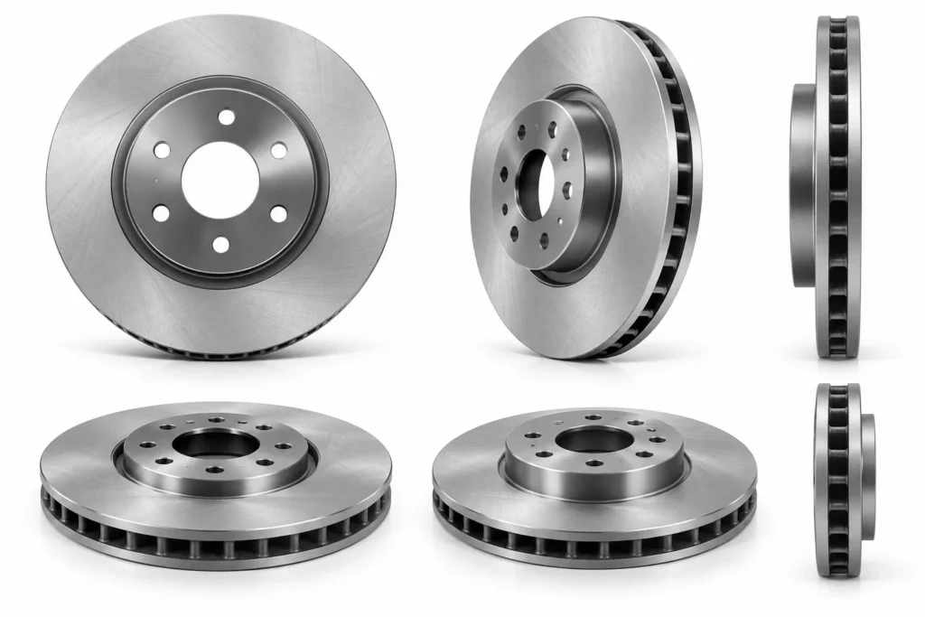
What is a vented rotor? It is a rotor made of two friction plates separated by internal cooling vanes. As the rotor spins, the vanes pump air from the center outward, carrying heat away. Vented rotors are standard on the front axle of nearly all modern cars and on both axles of many SUVs and trucks.
For a detailed comparison of cooling, weight and fitment, see our guide to Solid vs Vented Brake Rotors.
Drilled and Slotted Rotors
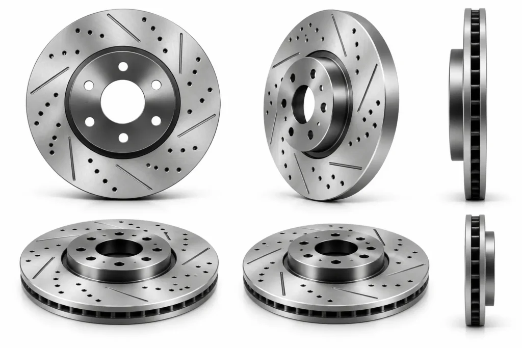
Drilled rotors have holes through the friction face; slotted rotors have shallow grooves machined into it. Slots help wipe away gas, water and pad debris, and both designs change the look of the brake. On street vehicles, the benefit is mostly appearance and wet-weather bite. Drilled holes can become starting points for cracks under severe heat, and both designs tend to increase pad wear and noise. For most replacement work, a plain face matched to the OE design is the safer choice.
Coated Brake Rotors
Coated rotors have a protective layer, often a zinc-flake or zinc-rich coating, applied to the hat, edge and vanes. The friction faces are either left uncoated or coated with a thin layer that wears off during the first stops. When customers ask about coated vs non coated rotor options, the difference is mainly corrosion: an uncoated rotor’s hat and vanes start to rust quickly in humid or salted-road conditions, which looks poor in the box and on the vehicle, and can affect hub seating if rust builds up on the mounting face.
What We Saw in Testing:
For one coated passenger-car rotor project, we compared 12 coated and 12 untreated samples in a salt-spray test at 35°C with a 5% NaCl solution. Visible red rust appeared on the untreated hat areas within 24 hours, while the coated samples showed no comparable red-rust coverage after 96 hours. For us, this test showed why coating choice matters particularly for replacement rotors stored or operated in humid and road-salt environments.
Those test conditions follow the neutral salt spray method defined in ISO 9227, which specifies a 5% sodium chloride solution at 35°C for assessing the corrosion resistance of metallic materials with or without corrosion protection. In North America, the same type of test is commonly run to ASTM B117, the standard practice for operating salt spray (fog) apparatus.
On the Purchase Order
If coating matters for your market, specify the coated areas (hat, edge, vanes), the coating type, and the required salt-spray hours under ISO 9227 or ASTM B117, along with the acceptance criterion, such as “no red rust on coated areas after X hours.”
06
What Are the Key Brake Rotor Dimensions?
Two rotors can look similar but still have different fitment. A few millimeters in diameter, thickness, height or bore can stop a rotor from fitting, push the friction ring out of line with the caliper, or create runout that turns into vibration. These are the dimensions that matter most.
Outer Diameter
The outer diameter sets where the pads contact the rotor and how much braking leverage the system has. A rotor that is too large will not clear the caliper; one that is too small leaves part of the pad hanging over the edge. Many vehicles offer more than one front rotor diameter depending on engine or trim, so diameter alone is a common source of wrong orders.
Rotor Thickness
New rotor thickness and minimum thickness are both critical. Thickness controls how the rotor fits between the pads and how much heat it can absorb. Typical passenger-car solid rotors are around 9–13 mm thick, while vented rotors are often 20–32 mm.
Overall Height
Overall height, sometimes called hat height, is measured from the hub mounting face to the outer friction face. It positions the friction ring in the caliper. A rotor with the right diameter and thickness but the wrong height can force the pads to contact the rotor off-center or rub the caliper.
From Our Production Floor:
In a 2026 aftermarket SUV front-rotor project, we machined a 312 × 25 mm vented rotor with an overall-height target of 46.30 ± 0.15 mm. During the first 80-piece inspection, 5 rotors measured 46.47–46.52 mm, outside our project tolerance. We corrected the machining fixture and checked the next 120 pieces, which held between 46.21 and 46.39 mm. It was a good reminder that two rotors can look identical while a small dimensional difference can still create a fitment problem.
Center Bore and Bolt Pattern
The center bore locates the rotor on the hub pilot. The bolt pattern is the number of stud holes and the diameter of the circle they sit on, known as the PCD (pitch circle diameter), for example 5 × 114.3 mm. Both must match the hub exactly. A rotor can share diameter and thickness with the correct part and still differ in bore or PCD.
Practical Rule
When a customer brings an old rotor, measure all five dimensions before cross-referencing. When ordering new SKUs, put all five, plus the vane type and side for directional rotors, on the purchase order.
07
What Are Runout, DTV and Brake Judder?
These three terms explain most vibration complaints. This section gives a short overview; each topic deserves, and will get, its own detailed guide.
Brake Rotor Runout
Lateral runout is how much the rotor face moves side to side as it rotates. It is measured with a dial indicator mounted on the knuckle, touching the friction face about 10–13 mm in from the outer edge. Runout itself does not usually cause immediate vibration. The problem is what it does over time: a rotor that wobbles brushes the pads at one point on each revolution, wearing that area unevenly and creating thickness variation. Our guide to Brake Rotor Runout: Causes, Measurement & Acceptable Limits covers the measurement procedure in detail.
Disc Thickness Variation (DTV)
DTV is the difference between the thickest and thinnest points around the friction ring. It is measured with a micrometer at 8–12 evenly spaced points, at the same distance from the edge. Even a very small variation, in the range of hundredths of a millimeter, can be felt as pulsation, because the pads follow the rotor’s thickness and transmit it back through the hydraulic system to the pedal. For the measurement method, see Disc Thickness Variation (DTV): What It Is and How to Measure It.
Brake Judder and the “Warped Rotor” Misconception
When a driver feels a pulsating pedal, the usual diagnosis is “warped rotors.” In most cases, the rotor has not bent. The vibration comes from thickness variation caused by runout, uneven pad deposits or uneven corrosion.
Industry Case — GM Brake Rotor Corrosion and Pulsation:
GM Technical Bulletin 00-05-22-002N, covering 2014 and earlier GM passenger cars and light-duty trucks, describes a case in which vehicles parked for extended periods in humid conditions can develop uneven rotor corrosion. The area covered by the brake pad may corrode differently from the exposed friction surface, creating thickness variation and subsequent brake pulsation.
For low-mileage “lot rot” cases of 0–321 km (0–200 mi), GM recommended attempting 10–15 moderate stops from 56–64 km/h (35–40 mph) with cooling time between stops before moving to rotor clean-up procedures. For more developed corrosion, the bulletin distinguishes cases around 3,200–8,000 km and flaking corrosion beyond that.
GM also states that lateral runout above 0.050 mm (0.002 in) will cause thickness variation to develop over time, with pulsation typically appearing within 4,800–16,000 km. The practical lesson is that pedal pulsation should not automatically be diagnosed as a “warped rotor”; hub mounting, lateral runout, corrosion and rotor surface condition all need to be considered.
Source: General Motors, Disc Brake Warranty Service and Procedures, Bulletin 00-05-22-002N, June 2013, archived by NHTSA.
We explain the full diagnosis in Brake Judder: Is the Rotor Really Warped?
08
What Are the Common Signs of Brake Rotor Problems?
Vibration or Pedal Pulsation
A pulsating brake pedal or shaking steering wheel during braking is the most common rotor complaint. As explained above, it usually points to thickness variation. Before replacing the rotor, check the hub face for rust or debris, measure runout and DTV, and confirm the wheel nuts were torqued evenly.
Grooves and Uneven Wear
Concentric grooves on the friction face come from hard particles trapped between the pad and rotor, or from pads worn down to the backing plate. That metal-on-metal contact is what drivers describe as brake grinding, a harsh scraping noise that usually means the pads are gone and the rotor is being damaged. A raised lip at the outer edge shows how much the rotor has worn.
Heat Spots or Cracks
Blue, dark or shiny patches on the friction surface are signs of overheating. Hard spots can form where the iron has changed structure, and these areas wear differently from the rest of the face. Hairline cracks running from the edge, or heat-check cracks across the face, mean the rotor should be replaced.
Rust and Corrosion
A thin layer of surface rust after rain or overnight parking is normal and wipes off after a few stops. Problems start when corrosion is uneven, as in the GM case above, when it pits the friction surface, or when rust builds up on the hub mounting face and creates runout.
Rotor Below Minimum Thickness
A rotor below its minimum thickness has lost the mass it needs to absorb heat. It runs hotter, cracks more easily and can let the caliper piston extend further than designed. It must be replaced.
09
When Should Brake Rotors Be Replaced?
Replace a rotor when it is at or below minimum thickness, when the surface is too damaged to restore, when runout or DTV cannot be corrected, or when there is cracking, heat damage or severe corrosion.
Shops sometimes resurface rotors instead. If you have wondered what does turning rotors mean, it is machining a thin layer from both faces on a brake lathe to restore a flat, parallel surface. Some rotors may be resurfaced if sufficient thickness remains, but replacement depends on rotor condition and vehicle specifications.
Minimum Thickness
Measure thickness with a micrometer at several points around the rotor, about 10 mm in from the outer edge. Compare the lowest reading with the MIN TH marking. Remember that resurfacing removes material, so a rotor close to minimum may become too thin once machined.
Severe Surface Damage
Shallow wear rings are normal. Deep grooves, a large lip, or a scored surface from metal-to-metal contact reduce the contact area and make new pads take longer to bed in. If machining would take the rotor below minimum thickness, replace it.
Excessive Runout or DTV
First rule out the hub. Clean the hub face and rotor mounting face, re-torque the wheel nuts in sequence, and measure again. If runout or DTV is still above specification, the rotor needs correcting or replacing, and the hub flange should be checked for runout as well.
Cracks, Heat Damage or Severe Corrosion
Cracks, heavy heat discoloration and deep corrosion are replacement conditions. They are also signs to look for the cause, such as dragging calipers, a sticking parking brake, unsuitable pads or a vehicle used for heavy towing.
10
How Do Brake Pads and Rotors Work Together?
Pad-to-Rotor Contact
The difference between rotors and brake pads is simple: the pad is the softer, replaceable friction part, and the rotor is the harder metal surface it presses against. But they work as a single friction pair. Braking performance depends on how evenly the pad face contacts the rotor face. Full, even contact gives smooth braking and even wear; partial contact creates hot spots, noise and uneven deposits.
Rotor Surface Condition
A new pad has a flat face. If the rotor is grooved, lipped or glazed, the pad touches only the high points at first. Braking feels weak, the pad overheats in small areas, and noise is more likely. That is why rotor condition should be checked at every pad change.
Transfer Layer and Bedding
During bedding, the pad deposits a thin, even layer of friction material on the rotor. The pad then works against this layer. An even layer gives consistent friction; uneven deposits create thickness variation and vibration.
A typical bedding procedure, which should follow the pad maker’s instructions where available, looks like this
- In a safe location, make 8–10 moderate stops from about 60 km/h down to about 10 km/h without coming to a complete stop.
- Make 2–3 firmer stops from about 80 km/h to 10 km/h, again without stopping completely.
- Drive for several minutes with light braking to let the brakes cool.
- Avoid holding the brakes hard while stationary when they are hot, which can imprint pad material on the rotor.
Why New Pads Do Not Always Require New Rotors
New pads do not automatically need new rotors. If the rotors are above minimum thickness, within runout and DTV limits, and free of deep grooves, cracks or heat damage, they can be reused. Many vehicles go through two sets of pads per set of rotors. The decision should come from measurement, not habit.
11
How Are Brake Rotors Manufactured and Inspected?
How a rotor is cast, machined and inspected decides whether it stays flat and quiet in service. Here is the process in outline; a full walkthrough will follow in our article “How Are Brake Rotors Made?” You can also see the process on our brake parts factory page.
Casting and Machining
- Melting and chemistry control: iron is melted and the chemistry adjusted to the target grade.
- Molding: rotors are usually cast in sand molds. Vented rotors need sand cores to form the internal vanes.
- Casting and cooling: controlled cooling sets the graphite structure and hardness.
- Cleaning: sand and scale are removed by shot blasting.
- Machining: CNC lathes turn both friction faces, the hat, the mounting face and the center bore. Bolt holes are drilled.
- Balancing: each rotor is checked for imbalance and corrected by small cuts on the edge where needed.
Surface Finishing and Coating
The friction faces receive a final turned or ground finish to a controlled roughness. Coated rotors then have the hat, edge and vanes coated, with the friction faces masked or given a thin layer that wears off quickly. Packaging must protect the faces from moisture and impact.
Thickness and Dimensional Inspection
Every batch should be sampled for outer diameter, thickness, overall height, center bore, bolt circle and hole diameter against the drawing, plus hardness and, where specified, metallurgy. Directional rotors are checked for correct left/right marking.
Runout and DTV Inspection
Runout and DTV are measured on a fixture that mounts the rotor on its hub face, just as on the vehicle. Our quality control targets for brake rotors are ≤0.03 mm lateral runout and ≤0.015 mm DTV, with results recorded by batch.
Industry Validation Data — Brembo / GM:
The BRAKE Report reported that Brembo and GM spent more than 1,300 hours on design and CAE, 850 hours on dynamometer testing, and completed 40,000 miles of road testing while developing a performance brake upgrade for GM full-size trucks and SUVs. The system used 410 × 32 mm vented rotors; on one application GM reported a 42% increase in rotor area, intended to increase brake-system thermal capacity. It is a useful real-world example of why rotor development involves cooling geometry, structural integrity, corrosion, vibration, fatigue and road validation, not diameter alone.
Source: The BRAKE Report, citing Brembo, November 2019.
12
How to Choose the Correct Replacement Brake Rotor
Vehicle Application and OE Number
Step 1: Identify the vehicle: year, make, model, engine and trim. Get the VIN when the catalog shows more than one rotor option.
Step 2: Record the OE number or the current supplier’s part number. Check for supersessions, because OE numbers change when parts are updated.
Solid or Vented Design
Step 3: Confirm whether the original rotor is solid or vented, and for vented rotors, whether the vanes are straight or directional. Directional rotors need separate left and right part numbers.
Rotor Dimensions
Step 4: Confirm the outer diameter, thickness, overall height, center bore and bolt pattern. For uncertain applications, measure the old rotor.
Front or Rear Position
Step 5: Confirm the axle. Front rotors are usually larger, thicker and vented because they do most of the braking. Rear rotors are often smaller and solid, and some include a drum-in-hat for the parking brake. Are front and rear rotors the same? On almost every vehicle, no. They differ in diameter, thickness, height and sometimes design, so they must be listed as separate SKUs.
Cross-Reference and Purchasing List
Step 6: Cross-reference the OE or supplier number to the new part number, and confirm that the dimensions match.
Step 7: For new SKUs, request a sample and compare it with the old rotor before ordering volume. Check it on a flat surface next to the old part: diameter, height, bore, hole positions, vane direction and the MIN TH marking. A sample that “looks right” but differs by a millimeter in height is exactly the kind of mismatch that turns into returns.
Step 8: Put the confirmed specification on the purchase order:
13
Brake Rotors for Auto Parts Stores and Repair Shops
What Auto Parts Stores Should Check
For stores, rotors are bulky and heavy, so shelf space and freight cost matter more than with pads.
Building a rotor range step by step
- Export 12 months of rotor sales and lost-sales requests by part number.
- Group them by dimensions (diameter × thickness × height) to see which sizes drive volume.
- Stock fast movers deep, keep mid movers in moderate quantities, and supply slow movers on request.
- Check that every stocked SKU has a confirmed cross reference and a dimension record.
- Store rotors flat in their boxes, in a dry area, and rotate stock first-in, first-out, especially uncoated rotors.
Buying pads and rotors for the same vehicles together also simplifies replenishment. We support this on our brake parts solutions for auto parts stores page, including mixed-SKU orders and private label packaging.
What Repair Shops Should Check
For shops, most rotor comebacks are installation-related. Clean the hub face to bare metal, torque wheel nuts in sequence with a torque wrench, check runout, fit suitable pads and bed them in. Our brake parts solutions for repair shops page explains how we support vibration and noise diagnosis.
14
Frequently Asked Questions About Brake Rotors
Is a brake rotor the same as a brake disc?
Yes. In the brake disc vs rotor question, the two terms describe the same part. “Rotor” is more common in North America, while “brake disc” is more common in Europe and in technical documents.
How many rotors does a car have?
A car with disc brakes on all four wheels has four rotors. A car with front discs and rear drums has two. Some rear rotors also include a small drum inside the hat for the parking brake.
How long do brake rotors last?
Many rotors last roughly 50,000–70,000 miles (80,000–110,000 km), often through two sets of pads, but life varies widely with vehicle weight, driving style, pad type and climate. The deciding factor is measurement: thickness, runout, DTV and surface condition.
Can brake pads be replaced without replacing rotors?
Yes, if the rotors are above minimum thickness, within runout and DTV limits, and free of deep grooves, cracks or heat damage. If not, resurface or replace them before fitting new pads.
What causes brake rotor vibration?
Most vibration comes from disc thickness variation, which usually develops from lateral runout, uneven pad deposits or uneven corrosion. Rust on the hub face and unevenly torqued wheel nuts are common root causes.
What is the difference between solid and vented rotors?
A solid rotor is a single plate, used where braking loads are lower, usually the rear axle. A vented rotor has two plates with cooling vanes between them, which removes heat much better, so it is used on front axles and heavier vehicles.
Can rusty brake rotors still be used?
Light surface rust is normal and wipes off after a few stops. Rotors with deep pitting, flaking, uneven corrosion under the pad area, or rust on the hub mounting face should be resurfaced or replaced.
Should brake rotors be replaced in pairs?
Yes. Do rotors come in pairs? They are usually sold individually, but they should always be replaced in pairs on the same axle, so both sides brake evenly and the vehicle does not pull.
15
Final Thoughts
Whether a replacement rotor suits a vehicle and its use comes down to six things working together:
Get the dimensions wrong, and the rotor never fits. Get the fitment right but ignore runout, and the vehicle comes back with pulsation. Choose the right design for the axle and climate, measure before replacing, and write specifications on the purchase order rather than relying on appearance.
If you are building or reviewing a rotor range, send us your OE numbers, aftermarket references, existing supplier numbers or your Excel purchasing list. We will match the rotors, confirm the critical dimensions, flag any references that need checking, and prepare a quotation for your full list.